 Industrial Solution Finder
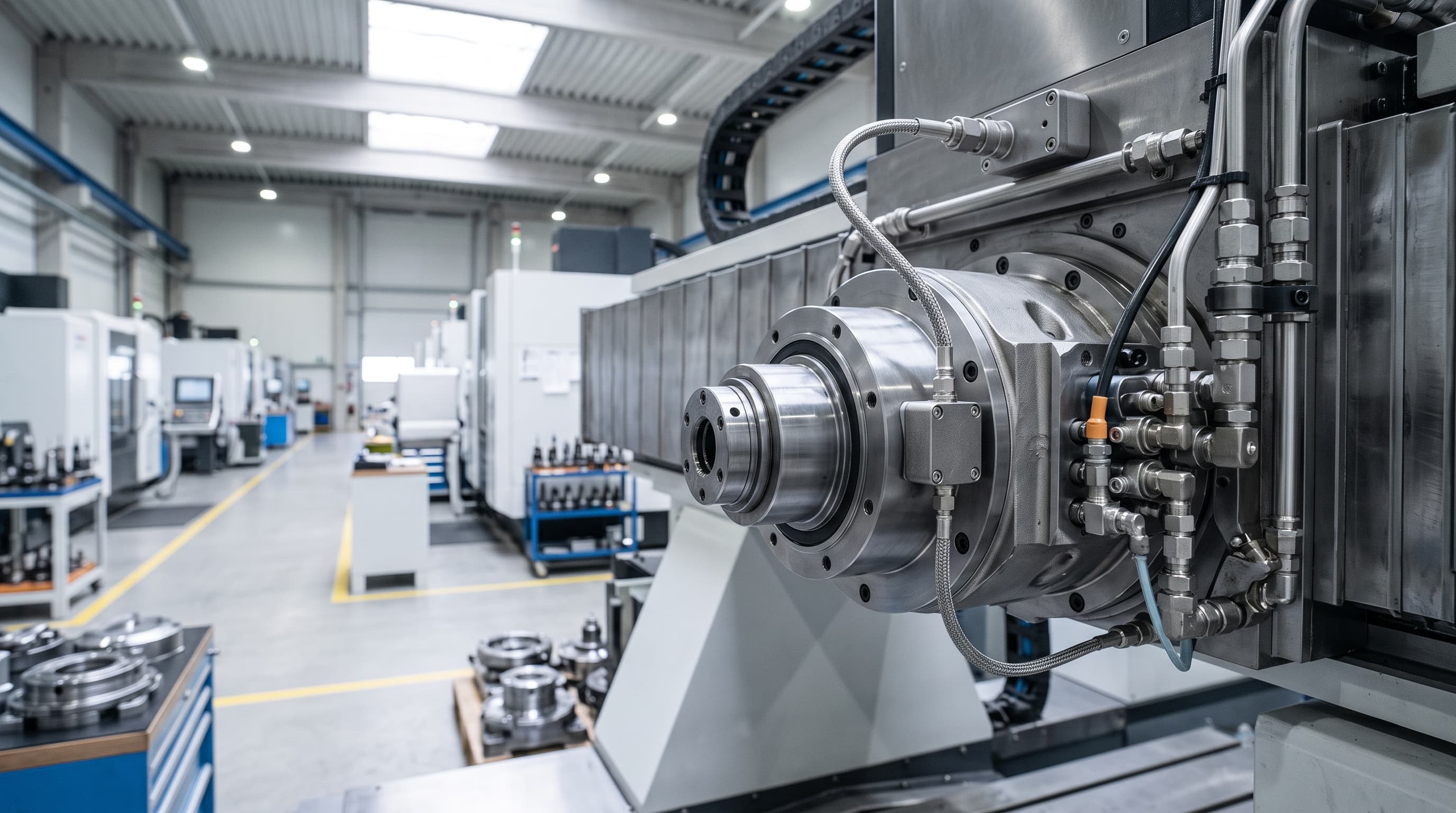
In 8,000–15,000 RPM CNC spindles, edge AI detects progressive subsurface fatigue 14–60 days ahead; sudden tool crashes or lubrication dry-out cannot be predicted in advance.
- Kinematic Baseline Configuration: Enter bearing part numbers into the edge monitoring firmware to calculate theoretical fault multipliers (BPFO, BPFI, BSF, FTF) relative to the variable drive spindle RPM.
- Sensor Installation and Cabling: Bolt hermetically sealed piezoelectric or wideband MEMS accelerometers in radial and axial orientations directly on the front and rear bearing retainers using shielded twisted-pair industrial wiring.
- Operational State Gating: Interlock vibration sampling with CNC numerical control states via fieldbus (such as OPC UA, PROFINET, or MTConnect) so data acquisition occurs during standardized warm-up or idle spindle sweeps rather than erratic roughing cuts.
The Physics of Spindle Degradation: Why Legacy Monitoring Fails
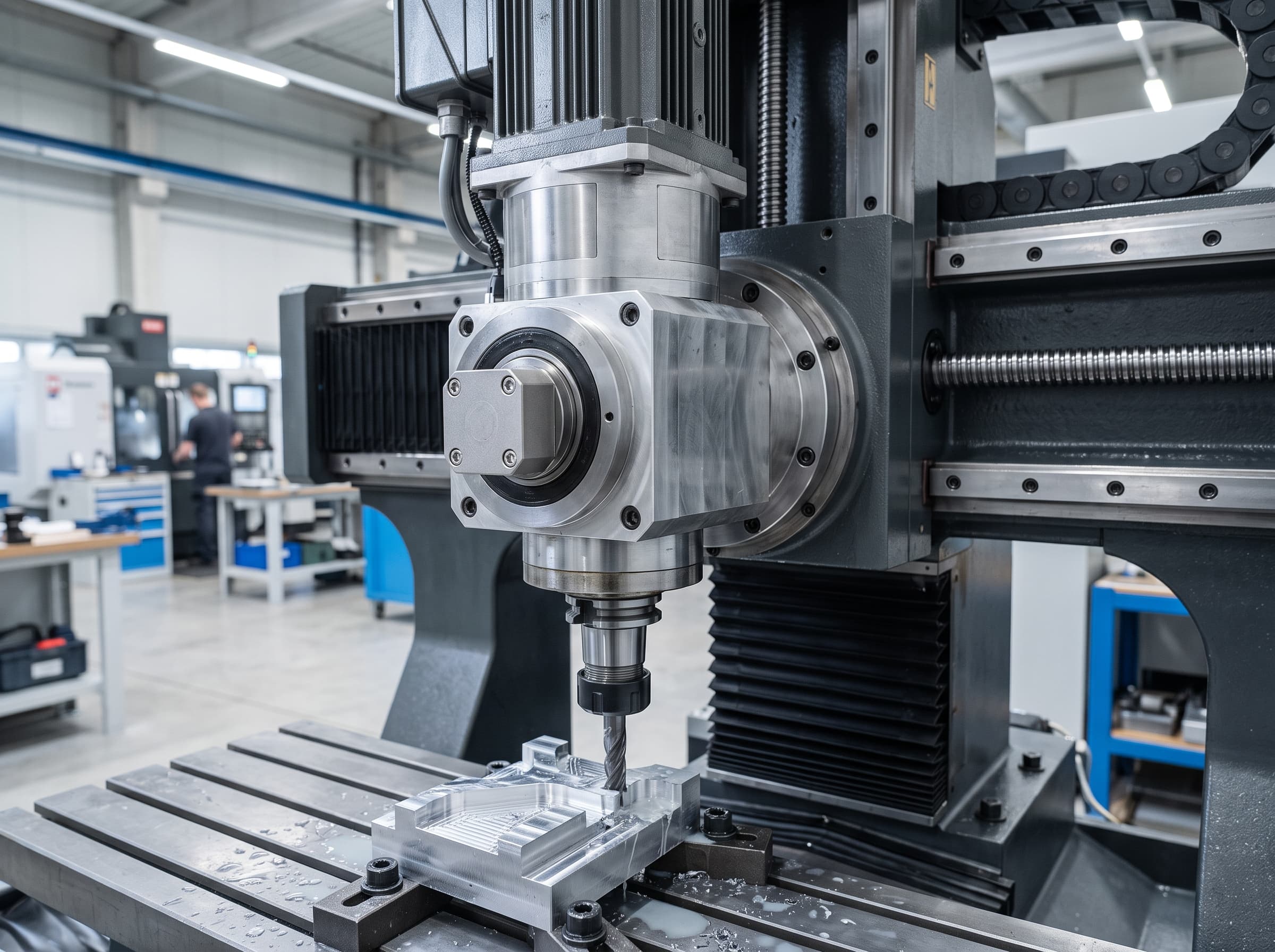
Computer numerical control (CNC) machine tool spindles operate at high rotational velocities under demanding cutting forces, dynamic radial loads, and tight dimensional tolerances. Inside these precision electro-spindles, super-precision angular contact ball bearings or hybrid ceramic bearings provide shaft stiffness and rotational accuracy. However, bearing degradation remains the single most prominent root cause of rotating machinery breakdowns in precision manufacturing, contributing to approximately 50 percent of all catastrophic mechanical disruptions on the shop floor1. When a spindle bearing loses structural integrity, thermal runaway and radial runout follow rapidly, resulting in ruined workpieces, damaged tooling, and emergency rebuild expenses that often reach tens of thousands of dollars.
Traditional preventive maintenance routines rely on calendar-based bearing replacements, periodic manual grease replenishment, or human acoustic checks. Unfortunately, bearing degradation does not follow a linear time path. Fatigue spalling, raceway micro-cracking, and lubricant starvation initially produce minute, high-frequency stress waves that generate minimal low-frequency casing displacement or perceptible heat. By the time an operator hears chatter, feels chassis vibration, or notices surface finish degradation on the finished part, the bearing has already entered terminal structural failure, risking weld seizure with the spindle shaft.
Signal Demodulation and Characteristic Defect Frequencies
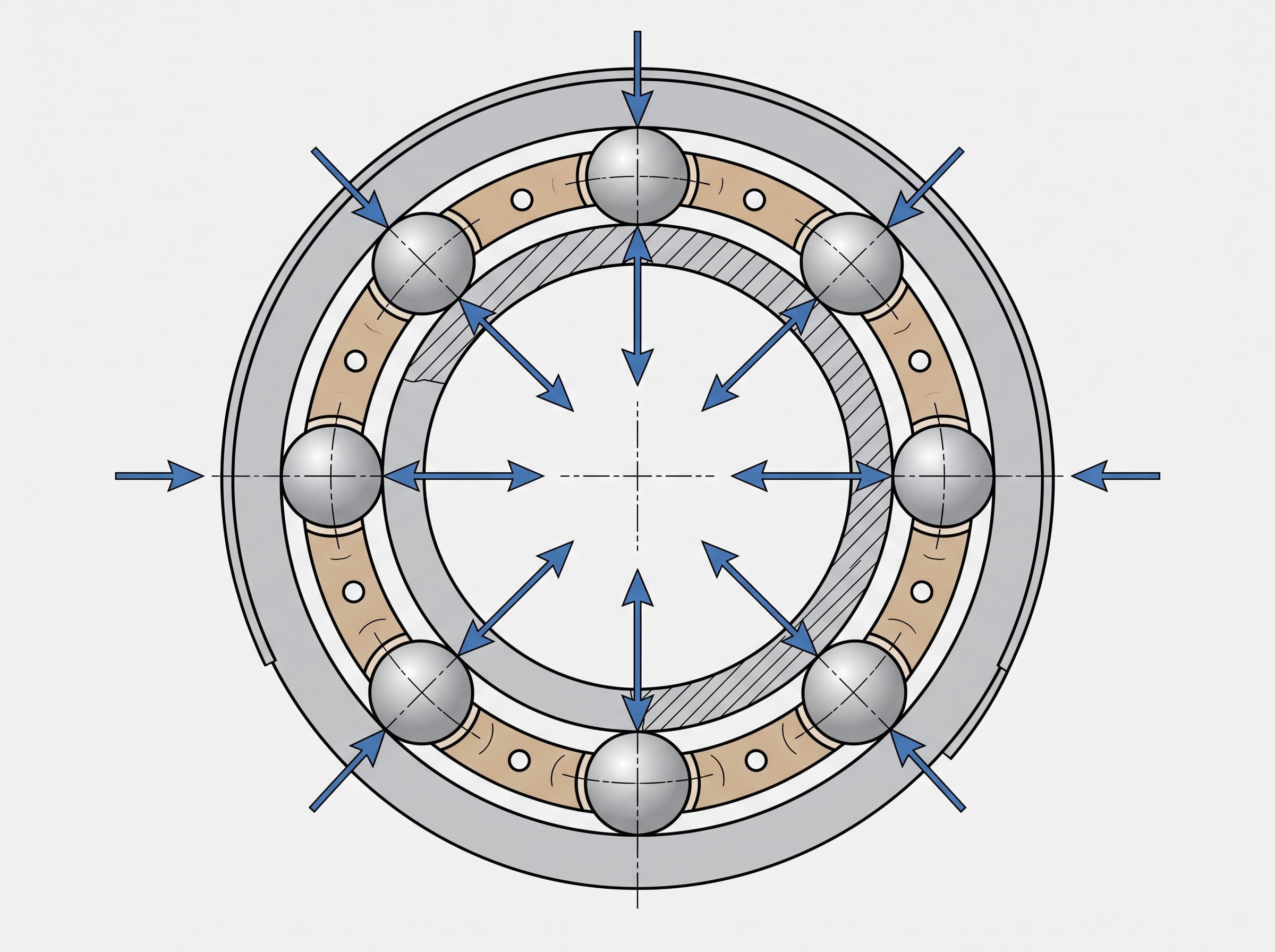
Every rolling-element bearing possesses deterministic geometric characteristics that govern the motion of its internal components. When a microscopic subsurface defect or surface pit develops on a specific raceway or ball, each contact event creates an impulsive impact. These periodic impacts produce mechanical vibrations at frequencies directly tied to shaft rotational speed and internal bearing geometry. Reliability engineers track four core bearing defect frequencies: Ball Pass Frequency Outer Race (BPFO), Ball Pass Frequency Inner Race (BPFI), Ball Spin Frequency (BSF), and Fundamental Train Frequency (FTF) representing the cage assembly.
During the incipient stage of bearing failure, these recurring shock pulses exhibit very low mechanical energy, often buried beneath machining process background noise, gear engagement hum, and cutting tool excitation. Conventional Fast Fourier Transform (FFT) analysis on raw vibration signals routinely fails to detect them because low-frequency structural vibration masks micro-amplitude impulses. Capturing early fatigue requires high-frequency resonance demodulation, also known as envelope analysis. The analog or digitized raw signal passes through a high-pass or bandpass filter—typically centered between 2 kHz and 10 kHz—to isolate the bearing impact resonance band, followed by rectification and low-pass smoothing. Performing an FFT on the extracted envelope reveals the periodic impact repetition rates matching BPFI or BPFO, exposing nascent raceway micro-spalling weeks before failure3.
The physical transmission of these shock pulses is heavily influenced by the spindle's lubrication method. Spindles lubricated with long-life synthetic grease (typically rated for spindle speeds up to 10,000 to 12,000 RPM) exhibit substantial internal hydrodynamic damping. The thick grease matrix absorbs and dampens acoustic emissions and micro-impact shock waves above 5 kHz, requiring accelerometers with superior signal-to-noise ratios and specialized low-frequency envelope thresholds to resolve faint BPFI peaks. Conversely, high-speed motorized spindles operating above 12,000 RPM often employ oil-air lubrication systems, where micro-metered droplets create an ultra-thin elastohydrodynamic film. This minimal oil boundary introduces virtually no acoustic attenuation, allowing sharp high-frequency transient stress waves to reach external casing sensors with minimal energy loss. However, the intermittent injection cycles of compressed air introduce low-amplitude pneumatic pressure pulsations, which edge AI signal filters must explicitly isolate from true rolling element defect harmonics.
Edge AI Architecture: Real-Time Inference at the Machine Tool
While envelope analysis extracts pristine fault spectra, running continuous predictive maintenance across multiple multi-axis CNC machines presents severe data bandwidth and latency challenges. High-precision spindle monitoring demands continuous sampling rates between 20 kHz and 50 kHz per axis to capture high-order harmonic spikes. Streaming raw multi-channel vibration data from dozens of CNC machines to a centralized cloud platform exhausts local factory bandwidth, incurs exorbitant recurring cloud compute charges, and introduces non-deterministic communication latencies of 50 to 500 milliseconds.
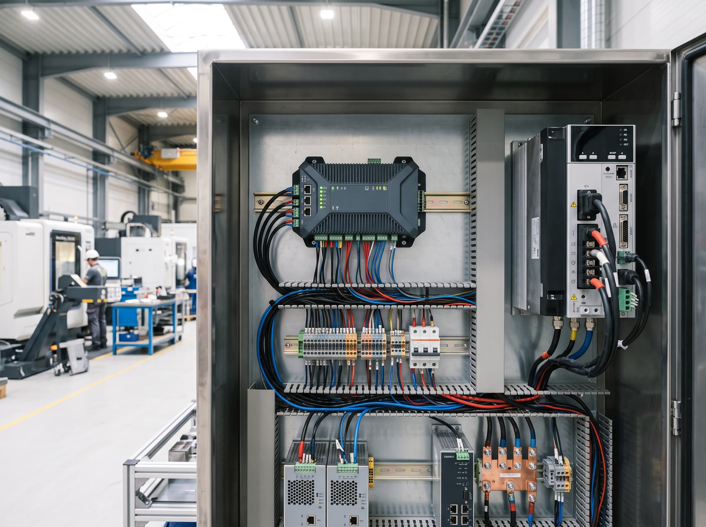
Edge artificial intelligence resolves this architectural bottleneck by embedding trained neural networks directly within local industrial controllers, smart sensor modules, or DIN-rail edge gateways positioned inside the machine tool control cabinet. Local edge processing filters high-frequency vibration streams and performs on-node anomaly inference, drastically reducing uplink bandwidth demands while avoiding cloud transmission delays2. By converting time-domain vibration bursts into spectral representations, such as short-time Fourier transform (STFT) spectrograms or continuous wavelet transform scalograms, compact Convolutional Neural Networks (CNNs) classify fault severities locally.
To execute these neural workloads on resource-constrained microcontrollers and edge application processors, modern predictive maintenance architectures deploy advanced neural compression techniques. Applying knowledge distillation, structural layer pruning, and 8-bit quantization-aware training compresses model weight footprint into tens or hundreds of kilobytes without degrading diagnostic precision1. The edge device computes health indices continuously, generating localized programmable logic controller (PLC) interlocks or feed-hold triggers if defect development accelerates toward imminent seizure.
Sensor Selection and Mounting Standards for Spindle Monitoring
Achieving actionable predictive accuracy depends entirely on input signal fidelity. Selecting the right transducer involves balancing frequency response, dynamic range, noise density, physical dimensions, and operational environment inside the machining enclosure. Coolant spray, high ambient temperature from built-in spindle drive coils, and intense electromagnetic interference (EMI) require ruggedized industrial encapsulation with minimum IP67 ingress protection.
| Sensor Technology | Frequency Bandwidth | Dynamic Range & Noise | Form Factor & Cost | Primary Failure Application |
|---|---|---|---|---|
| Piezoelectric IEPE Accelerometer | 0.5 Hz to 15+ kHz | Wide dynamic range (>100 dB), ultra-low noise density | Moderate footprint, higher unit cost, external signal conditioning | Early high-frequency bearing micro-cracking, envelope demodulation, high-speed motorized spindles |
| High-Bandwidth Digital MEMS | DC to 10 kHz | Moderate dynamic range (~80 dB), integrated ADC and digital filters | Ultra-compact footprint, low cost, direct SPI/I2C digital edge bus | Mid-frequency raceway flaking, general unbalance, secondary axis drives, cost-sensitive retrofits |
| Eddy Current Proximity Probe | DC to 10 kHz | Direct dynamic shaft displacement, immune to oil/coolant films | Requires precision radial mounting holes in housing, high calibration overhead | Hydrodynamic fluid-film bearings, direct shaft radial runout, thermal growth verification |
Sensor mounting mechanics dictate high-frequency signal transmission. High-frequency stress waves attenuate sharply across mechanical joints, threaded interfaces, and acoustic boundary layers. Magnetic mounts or adhesive pads introduce mechanical damping that severely rolls off frequency response above 2 kHz to 3 kHz, blinding the edge algorithm to incipient defects. Accelerometers must be stud-mounted using precision spot-faced, tapped holes directly into the cast iron or steel spindle nose housing as close to the front bearing pack as mechanically feasible, torqued to manufacturer specifications with a thin film of silicone grease to eliminate acoustic impedance gaps.
The mechanical coupling stiffness between the sensor casing and the spindle casting establishes a high-frequency mounting resonance. If stud torque is insufficient or if surface roughness on the spot face exceeds 1.6 micrometers Ra, this mounting resonance shifts down into the 5 kHz to 8 kHz region, artificially amplifying broadband machining noise and generating false positives in edge neural networks. Precision installation requires a dedicated flat-bottom counterbore perpendicular to the tapped hole within 0.05 millimeters total indicator reading (TIR), ensuring acoustic impedance matching up to the sensor's maximum calibrated bandwidth.
Step-by-Step Implementation Workflow for Machining Centers
Implementing an edge-AI vibration monitoring pipeline on production CNC machines requires a structured integration sequence to establish reliable statistical baselines and avoid operational false alarms:
- Kinematic Baseline Configuration: Enter bearing part numbers into the edge monitoring firmware to calculate theoretical fault multipliers (BPFO, BPFI, BSF, FTF) relative to the variable drive spindle RPM.
- Sensor Installation and Cabling: Bolt hermetically sealed piezoelectric or wideband MEMS accelerometers in radial and axial orientations directly on the front and rear bearing retainers using shielded twisted-pair industrial wiring.
- Operational State Gating: Interlock vibration sampling with CNC numerical control states via fieldbus (such as OPC UA, PROFINET, or MTConnect) so data acquisition occurs during standardized warm-up or idle spindle sweeps rather than erratic roughing cuts.
- Feature Engineering and Normalization: Compute time-domain metrics (RMS, peak-to-peak, kurtosis, crest factor) alongside bandpass-filtered envelope spectra and high-frequency energy values.
- Anomaly Detection Model Training: Deploy an unsupervised autoencoder or one-class classifier on the edge controller to learn the machine's healthy baseline vibration footprint across standard operational speed increments.
- Alarm Threshold and Automated Interlock Configuration: Establish tiered alert levels where moderate drift notifies maintenance via CMMS, while critical fault acceleration triggers a graceful cycle stop before tool breakage.
Operational state gating is essential for CNC environments. Vibration generated by aggressive milling inserts cutting through hardened steel or interrupted casting profiles produces high-energy transient spikes that dwarf underlying bearing signals. Trying to diagnose bearing spalling during variable heavy roughing frequently triggers false positive alerts. The edge AI firmware must coordinate with the CNC controller to sample vibration during repeatable operational windows, such as automatic tool change dwell periods, pre-shift spindle ramp cycles, or steady-state rapid traversals.
To extend health monitoring beyond idle dwells into active machining, the edge architecture must execute dynamic load filtering and cutting exception handling. During milling, cutting forces fluctuate dynamically as depth of cut varies, tools enter interrupted geometries, or regenerative chatter develops. By integrating a high-speed fieldbus feed that reads spindle motor torque, drive current, and commanded feed rate (via protocols like Fanuc FOCAS, Siemens Drive-CLiQ, or Beckhoff EtherCAT), the edge inference engine continuously tracks cutting engagement. When transient cutting torque spikes exceed baseline thresholds or when tool chatter is detected, the algorithm temporarily suppresses bearing fault inference or diverts the vibration frame into an isolated machining noise buffer. Concurrently, order tracking algorithms perform angular resampling based on spindle encoder pulses, dynamically synchronizing vibration samples to shaft angle and compensating for minute rotational speed droop under heavy cut loads so that BPFI and BPFO spectral bins remain razor-sharp.
Standards, Operational Limits, and Expert Verification Boundaries
Engineering teams must balance AI anomaly alerts against established international vibration criteria. Standard ISO 20816-3 provides foundational guidelines for evaluating overall broadband vibration severity on non-rotating parts for industrial machines operating between 120 and 30,000 r/min3. The standard divides machine operating status into four distinct evaluation zones: Zone A represents newly commissioned machinery, Zone B denotes acceptable long-term continuous operation, Zone C indicates unsatisfactory continuous performance requiring planned remediation, and Zone D warns of vibration levels severe enough to inflict immediate mechanical damage.
Crucially, ISO 20816-3 broadband velocity limits evaluate cumulative structural vibration typically within the 10 Hz to 1,000 Hz frequency spectrum. Incipient bearing defect impulses carry negligible broadband energy and will consistently register within safe Zone A or Zone B limits long after severe inner race micro-spalling has commenced3. Plant engineers must therefore utilize edge AI envelope and high-frequency spectral metrics as an early warning tier that precedes standard ISO broadband trip points by several weeks.
Edge AI vibration models identify statistical anomalies and pinpoint mechanical fault locations, but they do not replace formal mechanical root-cause audits. Once an edge device issues a persistent bearing fault warning, maintenance personnel must confirm the diagnosis using calibrated handheld spectrum analyzers, inspect lubrication clarity for particulate contamination, and verify shaft axial preload. If spindle replacement or precision rebuild is required, machine tool spindle rebuild specialists must perform final balancing and runout certification in a temperature-controlled cleanroom environment.
Predictive warning windows are not universal constants and must be qualified by specific machine classes and operational parameters. In precision 8,000 to 15,000 RPM machining center spindles experiencing incipient subsurface fatigue and microscopic raceway spalling (pits smaller than 0.5 mm), edge AI envelope tracking provides an advance warning horizon of 14 to 60 days before catastrophic seizure occurs. Crucially, this predictive window applies strictly to progressive mechanical wear; sudden external events—such as aggressive tool crashes, severe part collisions, or instantaneous lubrication pump failures—inflict immediate mechanical destruction that no predictive model can anticipate. Furthermore, lead time varies substantially based on mechanical boundary conditions: rigid preloaded angular contact sets operating under continuous high-feed milling degrade faster than spring-preloaded bearings under light finishing passes. Stationary outer ring defects (BPFO) often progress predictably over several weeks, whereas rotating inner ring spalls (BPFI) and rolling element damage accelerate rapidly due to concentrated dynamic stress reversals and centrifugal ball loading.
Frequently asked questions
Q. Under what operating conditions can edge AI provide a 14 to 60 day advance warning before spindle bearing failure?
A. This 14 to 60 day warning horizon applies strictly to gradual subsurface fatigue and raceway micro-spalling in 8,000 to 15,000 RPM spindles. It cannot predict sudden mechanical damage from tool collisions, workpiece crashes, or acute lubrication failure, which cause immediate catastrophic breakdown.
Q. Why can standard ISO 20816-3 broadband vibration monitoring miss early bearing degradation?
A. ISO 20816-3 focuses primarily on overall RMS velocity between 10 Hz and 1,000 Hz. Early bearing fatigue pulses produce micro-impact stress waves above 2,000 Hz that lack sufficient overall energy to cross broadband velocity alarm thresholds.
Q. How does spindle bearing lubrication (grease vs. oil-air) affect vibration monitoring sensitivity?
A. Grease lubrication introduces substantial viscous damping that attenuates high-frequency impact stress waves above 5 kHz, requiring higher sensor sensitivity. Oil-air systems provide minimal acoustic damping, allowing crisp stress wave transmission, but require AI filters to reject cyclic pneumatic injection pulses.
Q. How do edge AI systems avoid false alarms caused by aggressive cutting tool engagement?
A. Systems combine state gating during idle dwell periods with dynamic load filtering during active cuts. By monitoring drive current and torque via CNC fieldbuses, the edge AI suppresses inferences during heavy chatter or interrupted cutting and utilizes angular resampling to compensate for load-induced speed fluctuations.
Sources
- Efficient Bearing Fault Diagnosis for Edge Computing Using Grayscale Spectrograms and Hybrid Neural Model CompressionIEEE Access
- Using Vibration Monitoring, Edge AI and SPE/PoDL for Predictive Maintenance (SSZT037)Texas Instruments Incorporated
- ISO 20816-3:2022 Mechanical vibration — Measurement and evaluation of machine vibration — Part 3: Industrial machinery with a power rating above 15 kW and operating speeds between 120 r/min and 30 000 r/minInternational Organization for Standardization