 Industrial Solution Finder
Deploying an ISO 23247 twin on brownfield lines requires a 4-phase framework: OME telemetry audit, gateway sync testing, model fidelity verification, and gated closed-loop control.
Brownfield Constraints and the ISO 23247 Architectural Foundation
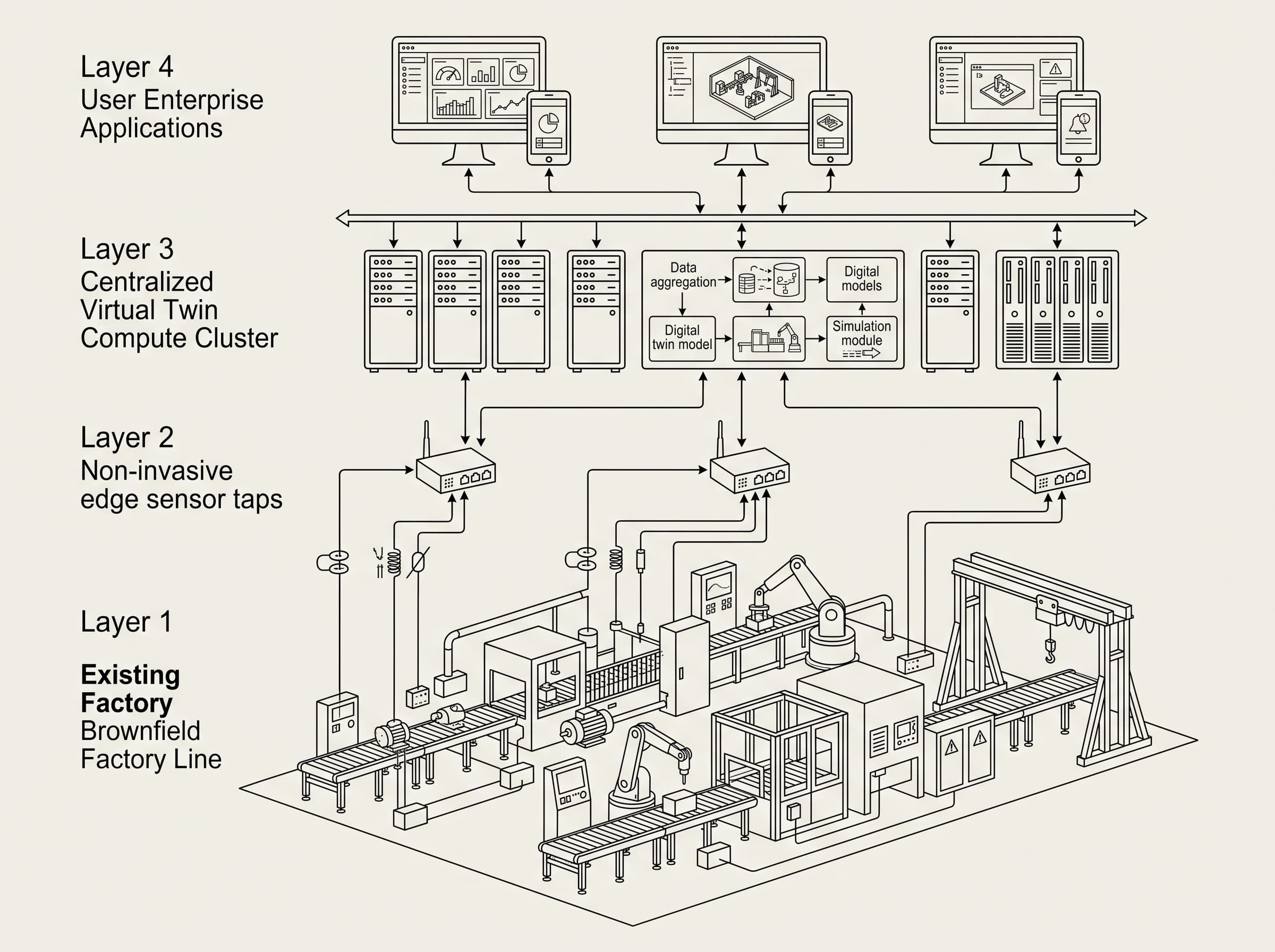
Brownfield manufacturing environments present unique engineering friction when implementing virtualized representations of operational assets. Unlike greenfield installations where native Open Platform Communications Unified Architecture (OPC UA) endpoints and pre-engineered network topologies exist, legacy facilities rely on fragmented programmable logic controllers (PLCs), serial fieldbuses, and isolated sensory islands. To prevent costly architectural rework, the International Organization for Standardization developed the ISO 23247 standard, which articulates a four-part reference framework explicitly separating observable physical assets from data communication, digital modeling, and external business software 1. Implementing this standard on existing operational infrastructure requires isolating the physical operational layer without altering validated machine cycle times or violating existing functional safety ratings.
The reference architecture specified in ISO 23247-2 establishes four functional domains: the Observable Manufacturing Element (OME) domain, the Device Communication domain, the Digital Twin domain, and the User Entity domain 2. In a brownfield context, an OME encompasses physical machinery, cutting tools, automated transfer systems, or work-in-progress inventory. The principal challenge lies in retrofitting sensing and transport layers that conform to ISO 23247-4 without introducing signal noise, non-deterministic latency, or network oversubscription to legacy industrial buses 3. Consequently, plant operators must execute a staged validation sequence that systematically proves data integrity, synchronization determinism, and dynamic fidelity prior to granting virtual models any supervisory or closed-loop control capabilities over line operations.
Phase 1: OME Auditing and Fit-for-Purpose Boundary Definition
Validation begins at the physical layer by defining explicit boundaries for each target OME in accordance with ISO 23247-1 principles, which mandate that all digital representations must be strictly fit for purpose rather than exhaustive duplications of the physical world 1. Engineers must catalogue every asset within the pilot cell, documenting mechanical operating envelopes, ambient thermal fluctuations, machine controller cycle limits, and legacy firmware revisions. A common failure mode in brownfield rollouts is over-scoping the digital twin, where teams attempt to model multi-physics finite element parameters when the actual operational objective is merely predictive spindle bearing health or tool wear cycle optimization, an operational scoping hazard underscored in architectural reviews of the standard 4.
During this initial phase, the engineering team establishes the static and dynamic attribute baseline codified in ISO 23247-3 5. Static attributes include equipment kinematic models, rated power limits, electrical schematic parameters, and original manufacturer tolerance thresholds. Dynamic attributes encompass high-frequency accelerometer streams, servo drive currents, and thermal sensor outputs. While ISO 23247-3 standardizes information structures and dynamic state representations without specifying numerical operational timing thresholds 5, plant engineering teams must define empirical target baselines suited to their process: for example, ensuring non-invasive telemetry polling does not stretch legacy PLC scan cycles by more than nominal operational margins (such as 1.0 to 1.5 milliseconds in discrete machining cells) to prevent watchdog interruptions 4.
Phase 2: Device Communication and Non-Invasive Data Gateway Validation
The second phase focuses entirely on the Device Communication entity defined in ISO 23247-2 and the information exchange mechanisms standardized in ISO 23247-4 [claim-2, claim-3]. Brownfield lines frequently feature obsolete communication interfaces, such as RS-485 serial loops, Modbus RTU networks, or proprietary fieldbuses that cannot natively publish JSON or MQTT payloads. Engineers must deploy secondary edge translation gateways, optical sensor taps, or secondary current transducers to extract telemetry out-of-band. Validation in this phase requires empirical verification that these edge collection nodes can normalize diverse shop-floor protocols into standardized information models like MTConnect or OPC UA companion specifications without packet loss, resolving interoperability gaps highlighted in technical evaluations of the standard 4.
Testing protocols during Phase 2 evaluate network determinism, clock drift, and transport latency across proximity and access networks. ISO 23247-4 delineates structural separation between local sensor networks and wider service distribution layers 3. To validate communication integrity, engineers inject synthetic network jitter and simulate bandwidth constriction up to 300 percent of projected baseline load. While normative ISO 23247 specifications define reference interfaces rather than mandating universal microsecond tolerances 4, brownfield engineering teams frequently adopt plant-level benchmarks for high-speed multi-axis motion and synchronous robotics—such as targeting Precision Time Protocol (IEEE 1588) hardware clock synchronization within 50 microseconds across telemetry streams—while requiring edge gateways to buffer data without dropping packets during network outages 3.
Phase 3: Digital Twin Entity Modeling and State Synchronization Testing
Once deterministic telemetry flows into the digital twin execution runtime, Phase 3 evaluates state synchronization and model fidelity as required by ISO 23247-3 5. A digital twin differs fundamentally from an offline simulation model because it maintains a continuously updated state reflecting the physical counterpart in near real time 1. In brownfield environments, physical machines exhibit mechanical wear, backlash, thermal distortion, and calibration drift that do not match original theoretical CAD drawings. Validation protocols must compare physical sensor ground truth against computational twin states over extended continuous machining or assembly shifts.
The validation protocol requires running dual-run shadow testing: the physical machine operates under typical production batch workloads while the twin processes incoming telemetry, generates real-time kinematic calculations, and calculates operational metrics within the Digital Twin entity 2. Because ISO 23247 standardizes architectural components and interaction concepts rather than mandating universal mathematical error boundaries or dynamic drift percentages 4, engineering teams must establish empirical pilot cell benchmarks. In discrete precision CNC milling and robotic pick-and-place PoC trials, teams commonly target virtual-to-physical state divergence under 3.0 percent across 100 continuous operational hours, while verifying that transient dynamic events are captured within 100 milliseconds for condition monitoring and 10 milliseconds for high-speed stress tracking.
| Validation Dimension | ISO 23247 Domain Reference | Brownfield Challenge | Recommended Engineering Benchmark | Automated Rollback Trigger |
|---|---|---|---|---|
| Sensor Non-Invasiveness | Observable Manufacturing Element (Part 1 & Part 2) | Legacy PLC memory overhead and cycle stretch | PLC cycle elongation kept within 1.0–1.5 ms; zero ladder logic modifications | PLC cycle fault or watchdog timeout detection |
| Ingestion Determinism | Device Communication Entity (Part 4) | Fragmented industrial protocols (Modbus, Profibus, serial) | Zero packet drop; IEEE 1588 time sync within targeted 50 µs motion envelope | Gateway buffer saturation exceeding 80% capacity |
| State Synchronization | Digital Twin Entity (Part 2 & Part 3) | Non-linear physical wear and unmodeled machine backlash | Virtual-to-physical divergence under 3.0% over 100 continuous operational hours | Telemetry drift exceeding 5.0% sigma variance |
| Actuation Safety | User Entity Integration (Part 2) | Unintended feedback loop to physical machine controls | 99.5% setpoint envelope conformance; shutoff response governed by ISO 13849-1 PLr calculations | Network packet timeout or safety boundary excursion |
Dynamic attribute validation also requires running controlled stress permutations. For instance, in subtractive computer numerical control (CNC) machining cells, the twin must be subjected to variations in raw material hardness and feed rate oscillations to verify that its surrogate analytical models do not suffer from mathematical divergence. Model parameters must be auto-tuned or systematically calibrated against physical inspection telemetry, such as coordinate measuring machine (CMM) dimensional data, to guarantee that cumulative virtual predictions remain bounded within predefined statistical process control (SPC) bands.
Phase 4: User Entity Integration and Gated Closed-Loop Actuation
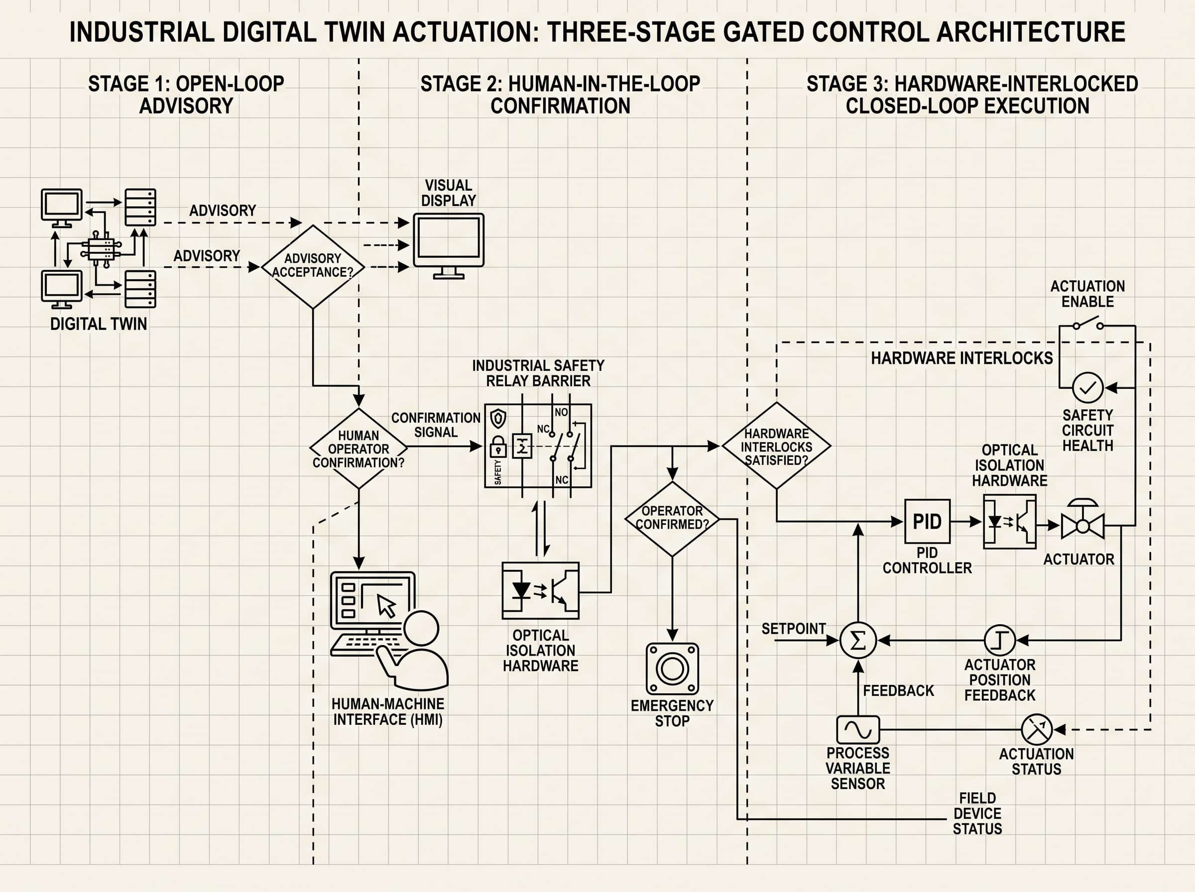
Phase 4 transitions the verified digital twin from a passive monitoring tool to an operational asset integrated with User Entities, which encompass Manufacturing Execution Systems (MES), Enterprise Resource Planning (ERP) databases, predictive maintenance schedulers, and supervisory setpoint optimizers [claim-2, claim-4]. Because ISO 23247 permits bidirectional information exchange, validation must rigorously enforce safety firewalls between algorithmic suggestions and machine execution 2. Brownfield equipment rarely possesses automated fault-recovery software, meaning an invalid setpoint command from a predictive optimization model could cause severe mechanical tool crashes or operator injury.
To achieve safe integration, engineering teams mandate a three-tier gating sequence: Open-Loop Advisory Mode, Human-in-the-Loop Validation Mode, and Gated Closed-Loop Execution. In Open-Loop Advisory Mode, the digital twin writes recommended parameter adjustments strictly to an engineering dashboard, where teams typically require an empirical baseline (such as 99.5 percent of proposed setpoints falling within safe operating envelopes over a 30-day evaluation) before advancing. Crucially, ISO 23247 does not standardize machinery safety trip times or hardware disconnect latencies [claim-2, claim-4]. Instead, all closed-loop control must strictly subordinate to certified functional safety standards such as ISO 13849-1 6. Under ISO 13849-1, safety response times and shutoff mechanisms are determined by machine-specific risk assessments, the required Performance Level (PLr), and safety distance calculations, ensuring independent, hardwired safety circuits disengage actuation whenever communication latency or operational anomalies exceed verified safety bounds 6.
Operational Governance, Security Guardrails, and Auditing Boundaries
Sustaining an ISO 23247 compliant digital twin across its operational lifecycle requires strict boundaries between IT network environments and Operational Technology (OT) assets. Legacy brownfield hardware was rarely designed with native encryption, role-based access control, or secure boot capabilities. Therefore, connecting brownfield OMEs to an ISO 23247-4 Device Communication network introduces substantial cyber-physical risk if not shielded behind IEC 62443 certified industrial security zones and conduits 3. Validation teams must conduct rigorous penetration testing, ensure all edge gateways enforce TLS 1.3 encryption, and isolate twin communication within dedicated operational VLANs.
Finally, manufacturing facilities must recognize the boundary between internal engineering validation and external regulatory certification. While an engineering team can validate that their twin architecture follows ISO 23247 reference topologies, any machine modification that bypasses existing emergency stop circuits, overrides certified safety interlocks, or alters safety-instrumented systems falls under mandatory machinery directives such as ISO 13849-1 and IEC 62061 6. Industrial solution architects must engage certified functional safety engineers and designated notified bodies whenever twin outputs cross the threshold from process parameter tuning to active motion override, preserving legal safety compliance throughout the smart manufacturing lifecycle.
Frequently asked questions
Q. What are the 4 validation phases required for brownfield ISO 23247 twins?
A. The four phases are: (1) OME Auditing and Boundary Definition, which establishes asset physical limits and verifies non-invasive data tap latency; (2) Device Communication Validation, which benchmarks protocol conversion and gateway buffer determinism; (3) State Synchronization Testing, which verifies physical-to-virtual model fidelity and tracks dynamic divergence; and (4) Gated Closed-Loop Integration, which advances sequentially from advisory dashboards to hardware-interlocked actuation with immediate rollback on control timeouts.
Q. What is the primary difference between a traditional simulation and an ISO 23247 digital twin?
A. Unlike traditional static simulation models that run offline with historical inputs, an ISO 23247 digital twin maintains continuous bidirectional or synchronized data exchange with an observable manufacturing element (OME) in real time.
Q. Can legacy PLCs without OPC UA connectivity support an ISO 23247 digital twin?
A. Yes. Brownfield lines utilize secondary edge gateways, non-invasive optical or current sensors, and protocol converters that extract raw data and translate it into ISO 23247-4 compliant network formats without altering legacy PLC code.
Q. How does ISO 23247 address functional machine safety during closed-loop control?
A. ISO 23247 standardizes information architecture and exchange rather than machinery safety directives. Therefore, any closed-loop actuation must be subordinated to certified hardware safety relays and systems governed by standards like ISO 13849-1.
Q. What is an Observable Manufacturing Element (OME) under ISO 23247?
A. An OME is any physical artifact, asset, process, facility, material, or personnel on the factory floor that possesses operational state information and is selected for virtual modeling.
Sources
- ISO 23247-1:2021 Automation systems and integration — Digital twin framework for manufacturing — Part 1: Overview and general principlesInternational Organization for Standardization (ISO)
- ISO 23247-2:2021 Automation systems and integration — Digital twin framework for manufacturing — Part 2: Reference architectureInternational Organization for Standardization (ISO)
- ISO 23247-4:2021 Automation systems and integration — Digital twin framework for manufacturing — Part 4: Information exchangeInternational Organization for Standardization (ISO)
- An Analysis of the New ISO 23247 Series of Standards on Digital Twin Framework for ManufacturingNational Institute of Standards and Technology (NIST)
- ISO 23247-3:2021 Automation systems and integration — Digital twin framework for manufacturing — Part 3: Digital representation of manufacturing elementsInternational Organization for Standardization (ISO)
- ISO 13849-1:2023 Safety of machinery — Safety-related parts of control systems — Part 1: General principles for designInternational Organization for Standardization (ISO)