 Industrial Solution Finder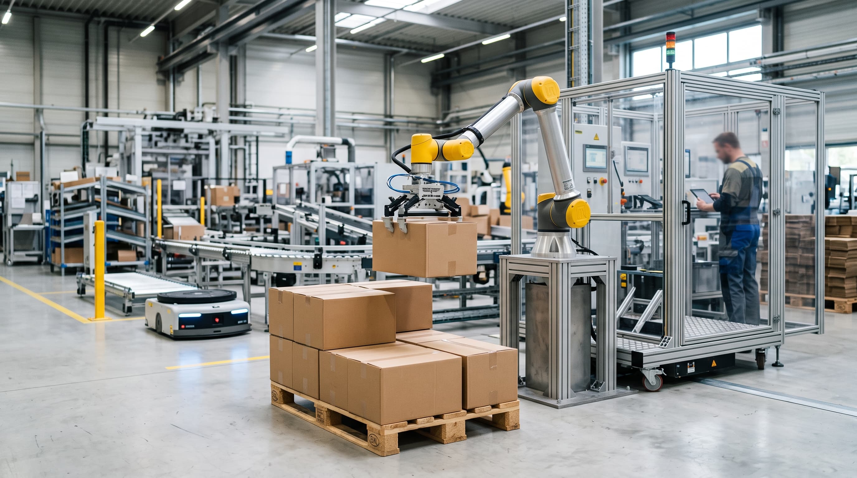
Calculate net payload by adding carton mass and tooling weight with a 20% dynamic margin against wrist torque curves. Size reach to pallet diagonals and add a lift column above 1.5 m.
Net Payload Sizing: Factoring End-of-Arm Tooling, Center of Gravity, and Inertia
Specifying a collaborative robot for end-of-line palletizing begins with calculating the actual working payload rather than relying on nominal data sheet ratings. The rated payload published by robot manufacturers represents the maximum allowable mass mounted directly to the mechanical wrist flange under static conditions at a minimal center-of-gravity offset, typically 50 to 100 millimeters 6. In operational palletizing cells, net product capacity is significantly lower because it must account for the mass of the end-of-arm tooling (EOAT), pneumatic vacuum manifolds, electrical valve blocks, quick-change chucks, and sensor brackets. A standard multi-bellows vacuum gripper designed for corrugated cartons weighs between 3.5 and 7.0 kilograms, while mechanical clamp mechanisms engineered for plastic totes or shrink-wrapped trays frequently exceed 10 to 12 kilograms 6. Subtracting this tooling deadweight directly reduces the permissible carton weight the robotic arm can continuously cycle without overstressing internal joint components.
Beyond static deadweight, packaging engineers must evaluate the distance of the payload center of gravity (CoG) and the resulting dynamic moment of inertia acting upon wrist joints four, five, and six. When gripping a large carton from an infeed conveyor, the center of mass frequently sits 150 to 300 millimeters away from the tool flange along the Z-axis, accompanied by lateral offsets during off-center picking. Major collaborative robot manufacturers—including Universal Robots (UR20/UR30), FANUC (CRX-20iA/L, CRX-25iA), Doosan Robotics (H-series H2017/H2515), and Yaskawa (HC-series)—publish explicit payload-versus-distance derating curves and allowable wrist moment ratings (measured in Newton-meters) alongside permissible moments of inertia (in kg·m²) [claim-1, claim-2]. For example, Doosan H-series load charts and FANUC CRX technical specifications dictate that exceeding a 200 to 250-millimeter CoG offset reduces effective payload capacity by 20 to 40 percent below nameplate ratings 6. If the dynamic overturning moment created during high-acceleration maneuvers exceeds joint torque boundaries, the robot controller initiates protective stops or subjects internal mechanical reducers—whether strain wave gears (harmonic drives) or cycloidal gears—to accelerated tooth wear and premature torsional fatigue 6. To absorb these high-inertia spikes during rapid carton reorientations, automation integrators apply a standard engineering rule of thumb: reserving an unallocated 15 to 20 percent dynamic inertia service factor above calculated peak static loads 6.
| Package Weight Class | Average EOAT Mass | Effective CoG Offset | Minimum Nominal Payload Rating | Recommended Elevation Support & Kinematic Limits |
|---|---|---|---|---|
| Light Cartons (0.5 – 5.0 kg) | 2.0 – 3.5 kg (Foam pad or compact venturi vacuum) | 80 – 120 mm from flange | 10 – 12 kg class cobot | Fixed floor pedestal (800 mm base); integrator kinematic layout indicates wrist singularity risk on Euro/GMA pallets above 1,400 mm stack height. |
| Medium Cases (5.1 – 12.0 kg) | 3.5 – 6.5 kg (Multi-cup vacuum manifold + ejector) | 130 – 220 mm from flange | 16 – 20 kg class cobot | Integrated 7th-axis lift column (500–800 mm stroke); recommended by packaging integrators for 5-to-7 layer GMA stacks reaching 1,600–2,100 mm height. |
| Heavy Cartons & Totes (12.1 – 20.0 kg) | 6.0 – 9.0 kg (Reinforced pneumatic clamp or vacuum) | 180 – 280 mm from flange | 25 – 30 kg class cobot | Synchronized telescopic column; dynamic simulation confirms avoidance of wrist joint over-rotation on 2,400 mm high-cube logistics pallets. |
| Bulk Packs & Sacks (20.1 – 35.0 kg) | 8.5 – 14.0 kg (Mechanical bag gripper or heavy clamp) | 220 – 350 mm from flange | 35 kg+ class or heavy industrial robot | Heavy-duty rigid industrial lifter column; mandatory to maintain path accuracy and eliminate mechanical deflection during high-inertia turns. |
Geometric Reach: 3D Kinematics, Pallet Diagonals, and Usable Envelope
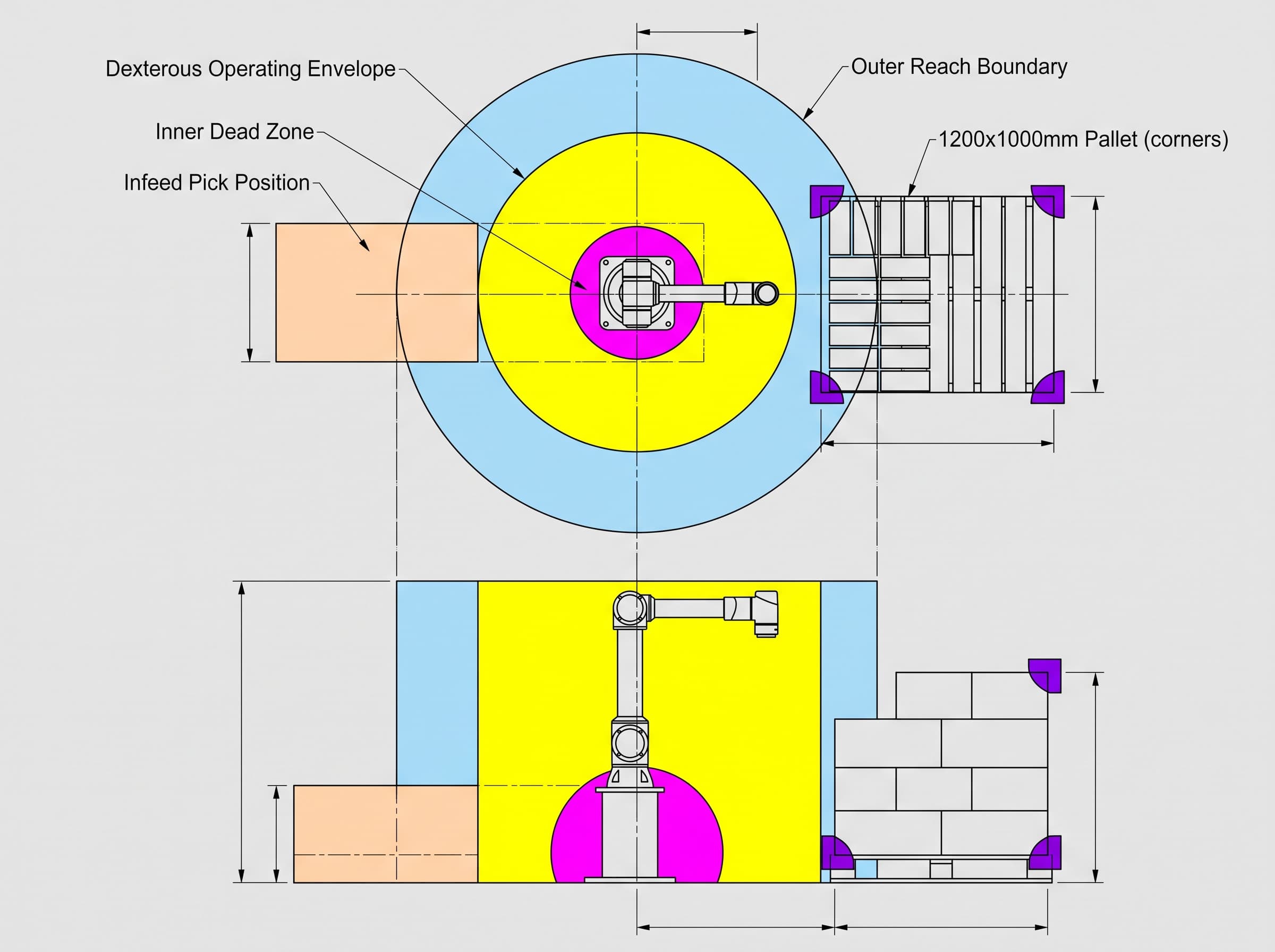
Evaluating collaborative robot reach for palletizing requires distinguishing nominal spherical radius from the dexterous operating envelope. Manufacturers specify reach as the maximum radial distance from the base rotation axis to the wrist center point when the mechanical arm is fully extended horizontally. However, in automated palletizing, the manipulator cannot operate at full horizontal extension because it must orient the gripper downward, perpendicular to the pallet deck, while avoiding collisions with neighboring carton tiers. This vertical orientation requirement, combined with the mathematical necessity to avoid singularities where inverse kinematic calculations demand unattainable joint angular velocities, reduces practical operating reach by 150 to 300 millimeters compared to raw catalog ratings 4. Operating near the physical perimeter forces abrupt joint reversals, velocity truncation, and axis-overload alarms.
Cell layout engineers must calculate the three-dimensional geometric distance to the outermost diagonal corners of standard logistics pallets. For a North American GMA pallet (1,219 by 1,016 mm / 48 by 40 inches) or a European pallet (1,200 by 800 mm), a cobot centered 300 millimeters from the pallet edge must reach diagonal drop coordinates between 1,350 and 1,450 millimeters away from its base center 4. Kinematic simulations of common 5-box interlocking patterns demonstrate that an arm with a nominal 1,300-millimeter reach can access near-side carton placements but encounters wrist singularities when attempting to place far-corner boxes on GMA formats 4. Furthermore, articulated arms exhibit an inner cylindrical dead zone directly around their base pedestal where the joints cannot fold tightly enough to position the tool faceplate downward. As an established integrator design guideline rather than a regulatory mandate, infeed pick conveyors should be positioned within 40 percent to 80 percent of the cobot's maximum reach to maintain fluid motion trajectories and avoid mechanical dead zones 4.
Vertical Elevation Challenges: The Seventh-Axis Telescopic Column
Vertical stack height imposes a rigid physical boundary on palletizing workcells. Modern distribution centers routinely specify finished pallet stacks between 1,600 and 2,400 millimeters, including the standard 144-millimeter wooden skid. On a fixed mounting pedestal, a six-axis collaborative robot reaches severe kinematic limits once stack heights exceed 1,400 to 1,500 millimeters 5. Kinematic modeling confirms that placing upper tiers on a 1,800-millimeter Euro pallet requires joints two and three to hyper-extend upward, forcing wrist joint five into acute flexion. In this awkward posture, allowable wrist torque drops sharply, and the arm risks collision with the top carton edges 5. Raising a static pedestal higher resolves upper-layer reach but prevents the arm from descending to low pallet decks (150 mm) or picking from standard 700-millimeter infeed conveyors 5.
The proven engineering solution for full-height logistics pallets is integrating a synchronized vertical lifting column, functioning as a coordinated seventh axis [claim-4, claim-5]. The telescopic column adjusts the base elevation of the cobot dynamically as pallet layers accumulate, maintaining the arm within its optimal kinematic sweet spot across all tiers from bottom to top 5. Sizing the vertical column requires calculating both vertical stroke (typically 500 to 800 millimeters) and the dynamic overturning moment exerted by the outstretched arm carrying maximum payload 5. Because an extended arm acts as a long cantilever, the lifting column must incorporate heavy-duty recirculating ball linear guide rails to prevent structural deflection under dynamic loads 5. Mechanical flexure exceeding two millimeters under dynamic braking causes carton misalignment, unstable pallet columns, and nuisance false-collision stops in sensitive joint torque sensors 5.
Throughput Calculations and ISO 10218-2:2025 Biomechanical Safety Integration
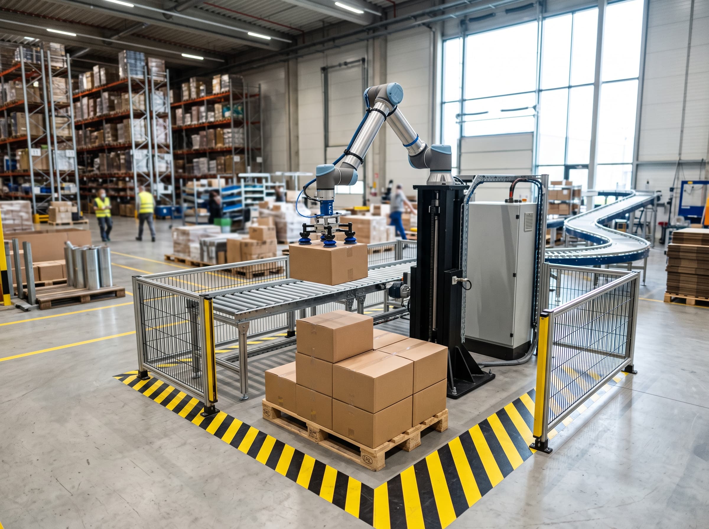
Sizing payload and reach requires direct integration with safety standards and cycle time modeling. A typical palletizing cycle involves a Cartesian path length of 1.8 to 2.4 meters round trip, encompassing carton pickup at a 700-millimeter infeed conveyor, a 300-millimeter vertical clearance lift, horizontal transfer across 900 to 1,200 millimeters, descent onto the pallet tier, and empty return 1. Under pure Power and Force Limiting (PFL) mode—originally specified in ISO/TS 15066:2016 and RIA TR R15.806, and now formally codified directly into the core requirements of ISO 10218-2:2025—the kinetic energy of a moving mass must not exceed human pain sensitivity thresholds during accidental contact 1. Handling a 12-to-16-kilogram combined payload (tool plus carton) limits permissible tool-center-point (TCP) transit speed to 250 to 500 millimeters per second, with acceleration capped at 1.0 to 1.2 m/s² 1. At these constrained speeds, completing a 2.0-meter round-trip trajectory requires 10 to 12 seconds, restricting fenceless throughput to only 5 to 6 cartons per minute.
Achieving industrial throughput rates of 8 to 13 cartons per minute requires transfer speeds between 1,200 and 1,800 millimeters per second, which exceeds biomechanical limits under PFL mode. Biomechanical limits originally published in ISO/TS 15066 Table A.2—now formally incorporated into the normative framework of ISO 10218-2:2025 under Clause 5.14.6 (Power and Force Limiting) and Annex M—establish strict force and pressure thresholds for quasi-static clamping, specifically 140 N and 120 N/cm² for the chest/sternum, and 150 N and 190 N/cm² for the upper arm deltoid muscle 1. When stacking cartons at chest or shoulder height, entrapment between an advancing carton and rigid pallet uprights presents severe quasi-static crushing hazards that PFL cannot safely mitigate at production velocities 1. System integrators therefore deploy Speed and Separation Monitoring (SSM) under ISO 10218-2:2025 clause 5.14.5 using safety laser scanners 1. The system configures an outer warning field that ramps speeds down upon operator approach, and an inner protective stop field that triggers a safety-rated monitored standstill if the boundary is crossed 1.
Engineering Workflow: Five-Step Sizing Procedure and Implementation Pitfalls
To prevent specification errors during procurement, engineering teams should execute a structured five-step sizing protocol. First, audit the package matrix to identify maximum carton dimensions, gross weights, and structural rigidity. Second, design the end-effector and quantify total tooling mass, pneumatic hose drag, and CoG offset, applying a recommended 20 percent dynamic inertia design margin against the manufacturer's published wrist moment derating curves [claim-1, claim-2]. Third, construct a 3D layout of pallet footprints (GMA or Euro) and infeed lines, verifying that corner coordinates remain within the dexterous reach envelope while placing the infeed between 40 and 80 percent of maximum reach to avoid base dead zones 4. Fourth, calculate required transfer speeds to meet case-per-minute targets and determine whether fenceless PFL or scanner-assisted SSM safeguarding is mandatory under ISO 10218-2:2025 [claim-6, claim-7]. Fifth, perform kinematic trajectory simulation in CAD software to verify that the robot maintains at least a 10-degree clearance angle from software and physical axis limits across all pallet tiers, an integrator best practice that prevents joint reversals and velocity fault trips 4.
The most common implementation failure in cobot palletizing is selecting an arm based solely on box mass while ignoring tooling weight and dynamic moment ratings 6. Integrators frequently discover late in commissioning that an arm rated for 12 kilograms cannot handle a 9-kilogram box because the vacuum manifold, blowers, and swivel brackets add 4.5 kilograms, driving the system into continuous over-torque faults. Another common oversight is failing to account for carton porosity, which requires high-flow blowers that add extra cantilevered mass at the wrist. Finally, project leaders must recognize that safety compliance under ISO 10218-2:2025, ISO 12100, and RIA TR R15.806 applies to the completed automated installation rather than the bare robot arm 1. Validating stopping distances, clamping clearances, and safety scanner reaction times via calibrated force gauges is mandatory before operating approval.
Frequently asked questions
Q. How do you calculate the required payload capacity for a palletizing cobot?
A. Add the maximum carton weight to the total deadweight of the end-of-arm tooling (grippers, manifolds, fittings, and sensors), and apply a 15% to 20% engineering margin. Always verify that the combined center-of-gravity offset falls within the manufacturer's published wrist moment derating curves.
Q. Why is published cobot reach different from usable palletizing reach?
A. Datasheet reach indicates maximum spherical extension at the wrist flange. Palletizing requires maintaining perpendicular downward gripper orientation while avoiding joint singularities and collisions, which reduces usable operating radius by 150 to 300 mm.
Q. When is a 7th-axis vertical lift column required for palletizing?
A. A vertical lift column is necessary whenever finished pallet stack heights exceed 1,400 to 1,500 mm. It eliminates kinematic overextension and joint torque limits on upper tiers while preserving low-level infeed pick capability.
Q. Can a collaborative palletizer achieve 10+ cartons per minute fenceless?
A. Under pure Power and Force Limiting (PFL) mode conforming to ISO/TS 15066 and ISO 10218-2:2025 biomechanical limits, moving 10+ kg payloads limits speeds to 250–500 mm/s, yielding only 5 to 6 cartons per minute. Higher throughput requires Speed and Separation Monitoring (SSM) with safety laser scanners.
Sources
- ISO 10218-2:2025 Robotics — Safety requirements — Part 2: Industrial robot applications and robot cellsInternational Organization for Standardization
- ISO/TS 15066:2016 Robots and robotic devices — Collaborative robotsInternational Organization for Standardization
- RIA TR R15.806-2018 Testing Methods for Power & Force Limited Collaborative ApplicationsAssociation for Advancing Automation
- Palletizing Robots for End-of-Line Automation and Application GuidelinesUniversal Robots
- EWELLIX LIFTKIT for Industrial Applications — Technical Specification and Application ManualSchaeffler medias
- FANUC CRX-25iA Collaborative Robot Technical Specifications and Allowable Wrist Load DataFANUC America Corporation
- UR20 Collaborative Robot Technical Specifications and User DocumentationUniversal Robots
- Doosan Robotics H-Series (H2017/H2515) Technical Specification and User ManualDoosan Robotics