 Industrial Solution Finder
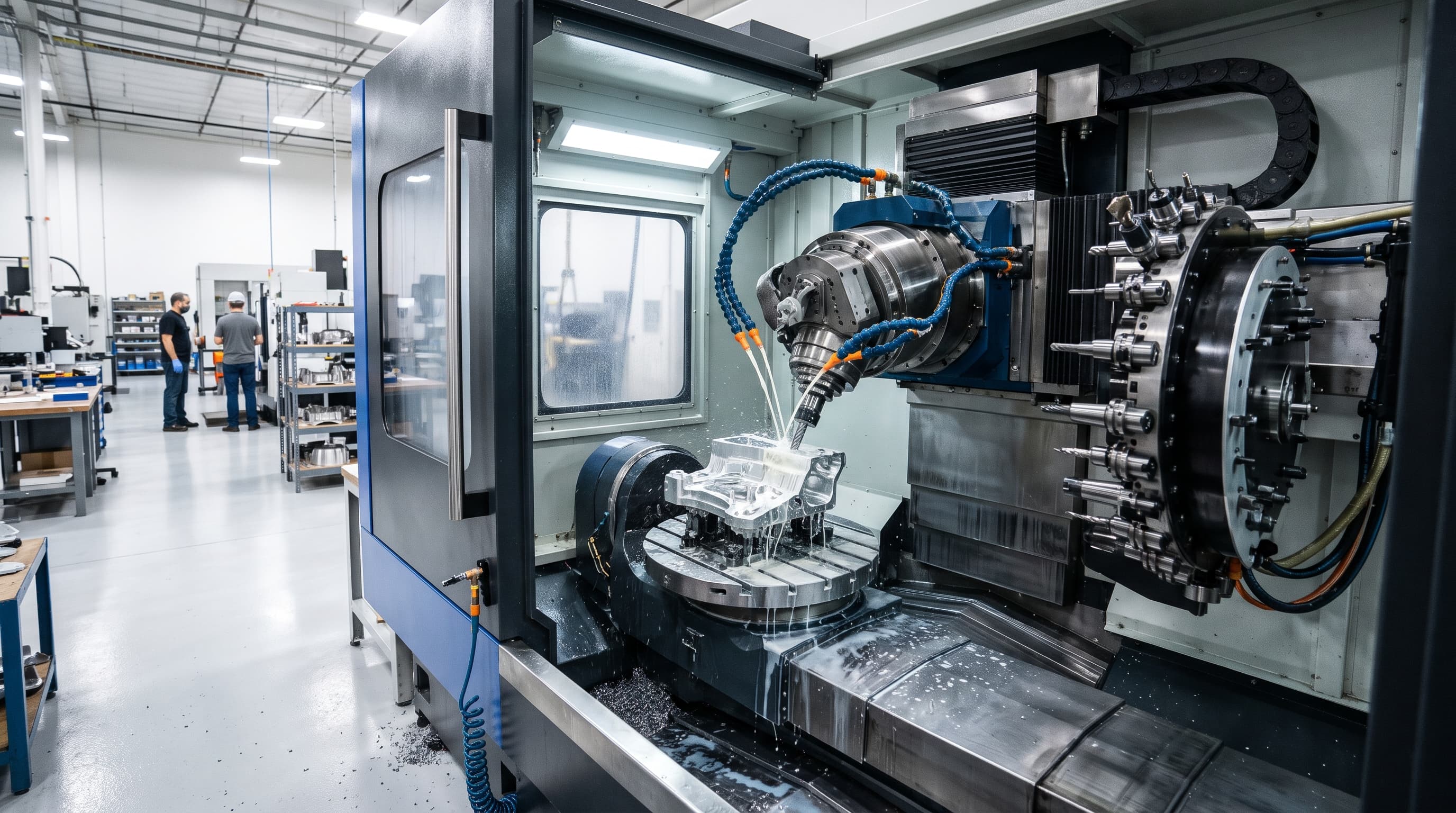
5-axis thermal compensation calculates multi-point temperature sensor data via real-time CNC transfer models to adjust linear and rotary axis coordinate offsets, counteracting spindle growth and lever-arm shifts before they cause dimensional drift.
In aerospace manufacturing, multi-axis machining cells encounter tight tolerances on complex geometries such as thin-walled engine casings, blisks, and structural wing ribs. While rigid toolholders and closed-loop optical feedback scales control mechanical positioning, thermal distortion remains an insidious root cause of out-of-tolerance parts. Manufacturing engineers frequently discover that an uncompensated machine tool operating within nominal limits in the morning drifts out of specification by mid-afternoon. Academic research indicates that thermally induced distortions contribute up to 75% of overall machining geometric errors in metal-cutting machine tools1. Addressing this requires understanding how internal heat generation and ambient fluctuations disrupt precision kinematics.
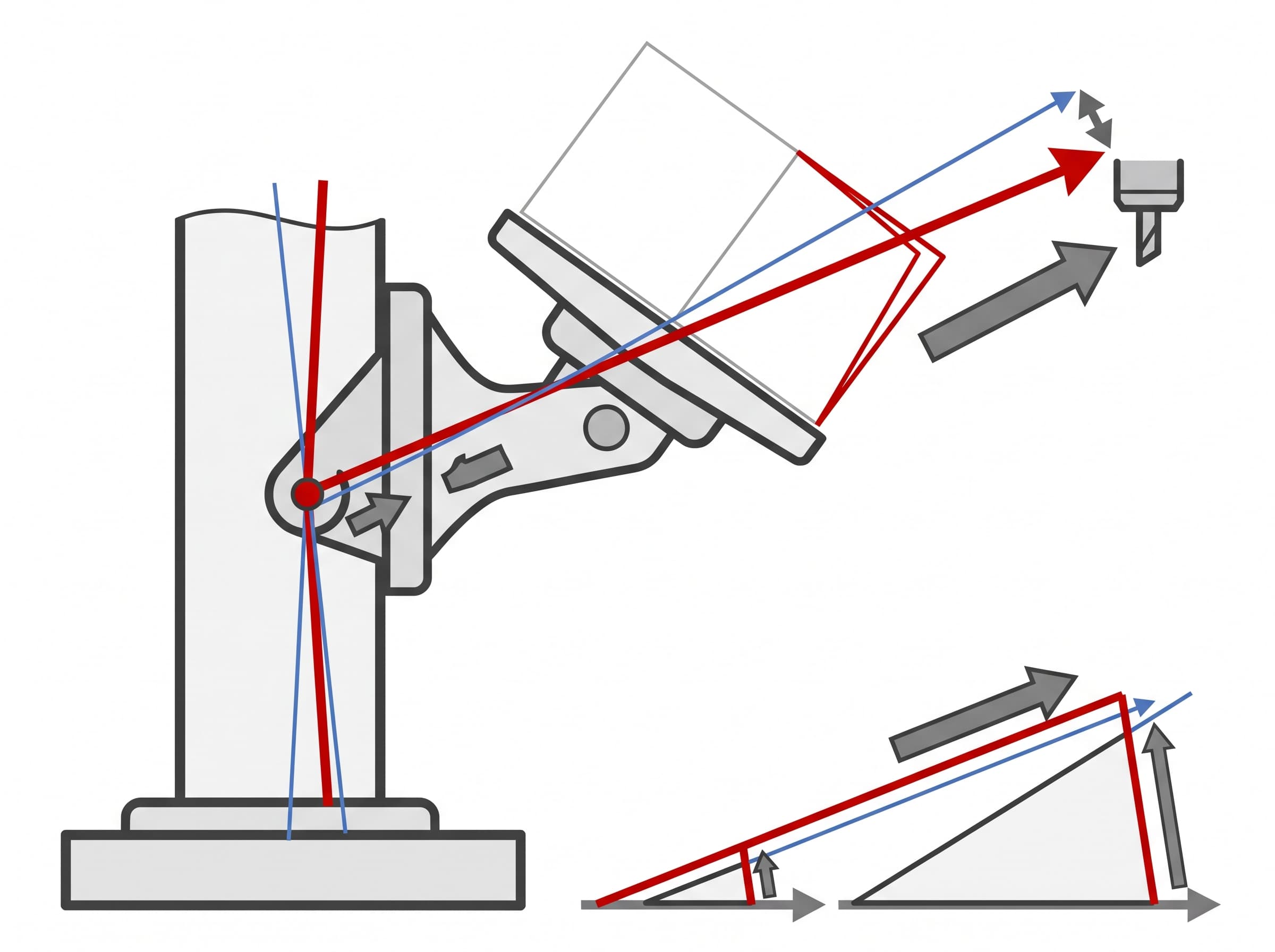
Kinematic Anatomy of Thermal Drift: Spindle Growth and the Lever-Arm Effect
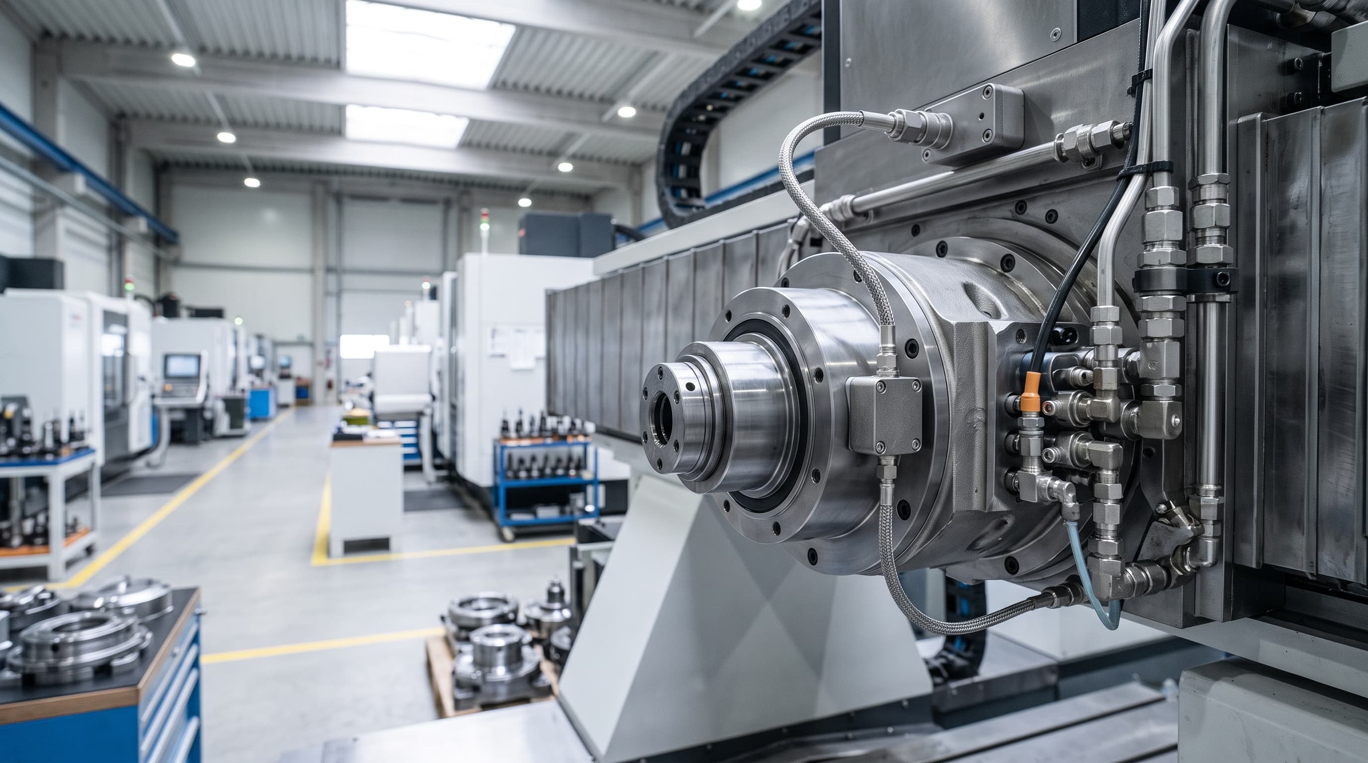
Thermal drift in high-speed 5-axis systems originates from two core domains: high-frequency internal friction within high-speed spindles and lower-frequency volumetric warming across large structural castings. High-speed spindle rotation produces intense localized heating around the hybrid ceramic or steel bearing packs and built-in electric motors. In compact to medium trunnion-style 5-axis machining centers with a 15 kW direct-drive spindle, unchilled thermal expansion commonly reaches between 20 µm and 40 µm in the axial Z direction as the unit warms from a cold start to an 8,000 rpm steady state, although active chiller loops can moderate this expansion to approximately 5 µm to 10 µm5. However, the linear elongation of the spindle cartridge represents only a fraction of the total tool center point error vector in multi-axis environments.
The primary complication in 5-axis architectures arises from swiveling rotary axes, such as B-axis tilting heads or C-axis trunnion tables. In standard 3-axis operations, an uncompensated 30 µm thermal drift on a 100 mm tool extension registers merely as an axial Z offset that often sits inside a generous print tolerance5. In contrast, under the specific kinematic conditions of compact to medium trunnion-style 5-axis machining centers, where the cutting tool and workpiece setup project 250 mm away from the kinematic center of rotation, that same structural instability causes the effective positional error to amplify into a 60 µm to 80 µm shift at the tool tip due to kinematic lever-arm multiplication5. Trunnion assemblies absorb heat from direct-drive torque motors, gearboxes, and ambient shifts, displacing the physical center of rotation by 20 µm to 40 µm between initial startup and thermal stabilization5.
Closed-Loop Compensation Architecture: Sensors, Transfer Functions, and CNC Offsets
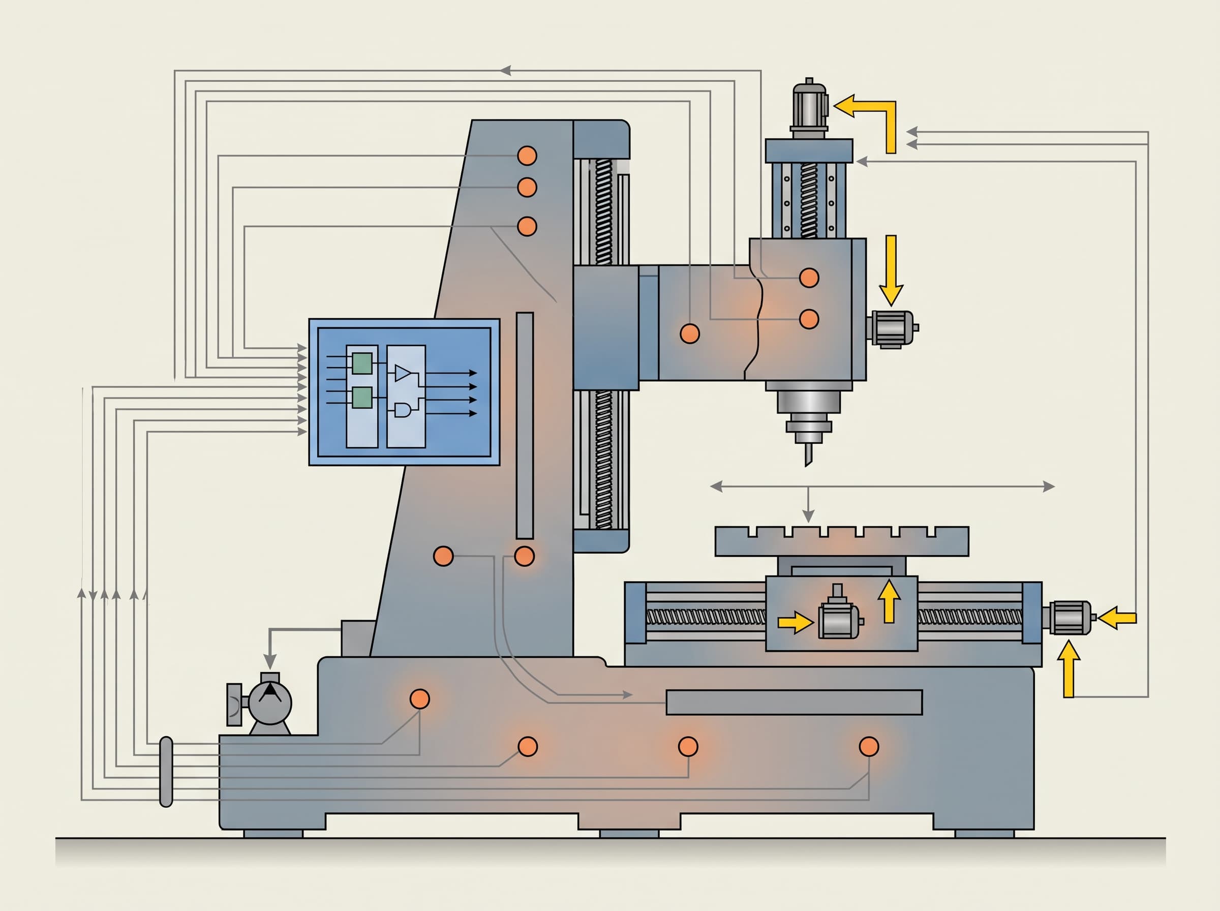
Modern thermal compensation bypasses the delay of manual touch-probe cycles by embedding dynamic mathematical models directly into the numerical control. Machine builders place arrays of resistance temperature detectors (RTDs) or fiber-optic thermistors near critical heat sinks: spindle bearing housings, ball screw support bearings, torque motors, and structural machine bed locations. Statistical optimization methodologies, such as Pearson correlation coefficient filtering, allow engineers to eliminate thermal sensor redundancy and isolate key measurement nodes—often monitoring bearing zones and internal housings to avoid interference from cooling circuits3. These real-time temperatures, paired with active spindle tachometer telemetry, feed algorithmic models running in parallel with the machine path interpolation cycle.
Within the CNC kernel, empirical transfer functions (TF) or machine learning algorithms evaluate the shifting thermal state every few milliseconds. Advanced implementations deploy random forests or regression algorithms to achieve over 90% accuracy in predicting spindle drift3. Rather than altering raw G-code part programs, the CNC injects micro-offsets directly into the axis servo loop via coordinate system transformations or dynamic kinematic work offset tables. This instantaneous correction continuously shifts the tool center point (TCP) and rotary centerlines, neutralising expansion before the cutting edge can gouge thin aerospace surfaces4.
Comparative Evaluation of Thermal Mitigation Approaches
Achieving tight volumetric tolerances across 24-hour manufacturing cycles requires selecting the correct combination of passive conditioning, physical thermal controls, and digital algorithms. Shop managers often weigh physical infrastructure investments, such as climate-controlled cleanrooms, against embedded software features provided by CNC OEMs. While physical chilling stabilizes localized hot spots, uncompensated structural drift across moving linear and rotary components still compromises high-precision surface blending.
| Mitigation Strategy | Working Principle | Primary Error Addressed | Strengths and Limitations |
|---|---|---|---|
| Environmental HVAC Control | Continuous air recirculation maintaining shop ambient temperature within tight limits | Macro shop floor diurnal expansion and contraction across structural machine castings | Mitigates external ambient drift; ineffective against high internal bearing friction and rotary motor heat |
| Active Chiller Loops | Recirculating temperature-controlled fluid through spindle jackets and hollow ball screws | Direct localized friction from spindle cartridge bearings and axis drive mechanisms | Reduces spindle Z-growth from 20-40 µm down to 5-10 µm; cannot eliminate non-linear kinematic pivot drift |
| CNC Real-Time Algorithm Compensation | Sensor-driven empirical transfer functions or regression updating servo offsets dynamically | Residual tool center point drift, kinematic pivot shift, and non-uniform axis expansion | Corrects dynamic thermal drift in real time via internal models; requires rigorous empirical calibration per machine |
Standardized Validation: Executing ISO 230-3 Thermal Testing
Validating the integrity of an installed compensation package demands rigorous adherence to international standards. The definitive framework is codified under ISO 230-3:2020, which establishes standardized testing codes to evaluate thermal distortions in machine tools2. This standard defines four mandatory measurement procedures: the Environmental Temperature Variation Error (ETVE) test, the rotating spindle thermal distortion test, the linear axes moving distortion test (applicable to NC machines across representative lengths up to 2,000 mm), and the rotary component distortion test2. The addition of Clause 8 specifically standardizes procedures for evaluating thermal effects generated by rotating heads and swiveling tables2.
Executing an ISO 230-3 validation involves mounting high-precision non-contact eddy current sensors or precision displacement indicators around a precision test arbor clamped in the spindle nose, referenced to a fixture nest on the pallet receiver. Over multi-hour operating cycles alternating between cold idling, peak spindle speeds, and rapid axis travel, the automated test fixture records relative drift between the tool holder and the workpiece setup2. By subtracting baseline ETVE data, metrology teams isolate residual compensation errors, demonstrating whether the machine tool delivers the thermal uncertainty limits necessary for safety-critical flight hardware.
Implementation Pitfalls and Technical Boundaries
Despite sophisticated software algorithms, thermal compensation can fail if base operating conditions deteriorate. A frequent failure point involves asymmetric coolants. High-pressure through-spindle coolant (TSC) delivers cutting fluid at variable temperatures directly through the center of the spindle cartridge, shocking the thermal equilibrium. If the coolant temperature is not conditioned to match the machine casting within ±0.5 °C, sharp thermal gradients occur across the rotating elements, producing rapid local contractions that dynamic compensation algorithms—tuned under steady-state dry conditions—cannot anticipate5.
Another vulnerability arises from unmonitored kinematic pivot degradation. Dynamic 5-axis thermal algorithms assume that the mechanical center of rotation wanders according to predictable thermo-elastic functions. However, if physical foundation anchoring shifts, structural leveling creeps, or rotary worm drives experience unmodeled mechanical wear, the software will apply compensation offsets against incorrect nominal coordinates. Consequently, machine shops must separate pure thermal drift from mechanical backlash or geometric misalignment by running regular volumetric ballbar or kinematic probing routines before trusting automated thermal offset scripts.
Frequently asked questions
Q. Can linear glass scales eliminate the need for thermal compensation?
A. No. While linear glass scales counteract expansion along the linear axis drive screws by closing the positional loop, they do not detect spindle cartridge growth, thermal bending of structural columns, or angular displacement at rotary table pivot points.
Q. How does cutting coolant temperature impact thermal compensation models?
A. Coolant variations introduce localized thermal shocks. If coolant temperature deviates from the machine bed temperature by more than ±0.5 °C, sharp thermal gradients develop across the spindle and casting, invalidating pre-calibrated steady-state compensation models.
Q. Why is thermal drift more destructive in 5-axis machining than in 3-axis setups?
A. In 5-axis systems, rotary axes introduce a lever-arm effect. A minor thermal shift at the trunnion or head pivot point is amplified significantly at the tool tip based on tool length and part stickout distance.
Sources
- Thermal issues in machine toolsCIRP Annals - Manufacturing Technology
- BS ISO 230-3:2020 Test code for machine tools — Part 3: Determination of thermal effectsBSI Knowledge / International Organization for Standardization
- The Thermal Error Estimation of the Machine Tool Spindle Based on Machine LearningMDPI Machines
- Thermal error compensation of a 5-axis machine tool using indigenous temperature sensors and CNC integrated Python code validated with a machined test piecePrecision Engineering
- Compensating 5-Axis CNC Thermal Drift in Rotary AxesIndustrial Monitor Direct